![]() email me - warrens@ns.sympatico.ca.
email me - warrens@ns.sympatico.ca.
Last changed 2 April 2005
 Refer to the schematic diagram to fully understand how the circuit works.
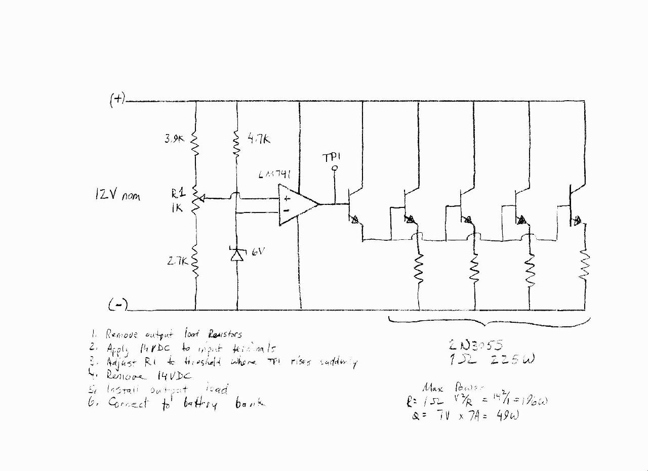
The circuit is essentially a variable output voltage power supply with a fixed load. As the input voltage attempts to increase above a set point determined by potentiometer R1 the op amp will increase the voltage across the load resistors. This extra current will load the source to maintain a maximum voltage. Excess energy is dissipated as heat.
The op amp inverting input is given a 6V reference by the zener diode and 4.7k resistor. The non inverting input voltage is determined by voltage dividing resistors, including a 1k potentiometer. As the battery voltage increases so will the non inverting input at the op amp. When it is the same as the non inverting input its output (TP1) will begin to raise rapidly. This will turn on the first transistor which acts as a buffer to the main pass transistors. The voltage at TP1 will automatically adjust to maintain both op amp inputs at the same voltage level.
An alternate to high power resistors is used car headlights. They can operate for long periods at full power and give a visible indication of how much excess power is being created. Two identical headlights can be connected in series for a 24VDC system.
To adjust the circuit, remove all load resistors and apply 14VDC to the circuit input terminals.
Monitor TP1 and adjust R1 until the output voltage rised suddenly.
Remove 14VDC from the input terminals and install the load resistors.
Connect the dump load to the battery bank.
Maximum power calculations
Resistor 14V x 14V / 1 ohm = 196 watts per resistor
Transistor 7V x 7A = 49 watts per transistor